This slideshow requires JavaScript.
Author: ietgar
Question – How to organize a list and run a test

Question
Can anyone tell me why when I draw a curve or any line it is not visible in the viewport? I am drawing it correctly so that is not the case. I have tried drawing it in different layers and changed the background color but that doesn’t solve the problem. It might be a setting that I accidently activated. It’s probably a quick fix. Please help
Laser Cutter file set-up

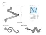
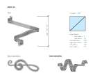
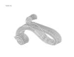
Treble Clef Bench
The bench is modeled after the profile of a treble clef symbol. The bench height varies in relationship to the human body and offers a few different seating accomodations. It is made out of tubular steel and steel rods. The main drivers include: the depth of the extension the bench runs along one axis, the different thicknesses of the bench along its curve based on the graphmapper properties or a the manipulation of a rhino drawn curve (along with its inputted bounds), and other drivers such as depth of the seat, radius of the steel tubes and rods, and number of rods.


Sitscape by Iris


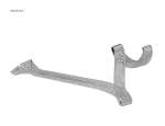
Sitscape is a seating system that the architecture firm, Hackenbroich Architects, designed to accommodate various relaxed positions. First, I had to analyze the object and locate the transition points within the form and create those specific section geometries with Curves. After building several curve geometries, I created interpolation points that ran across all the sections. I then used a NetworkSurface, referencing the interpolation guide points and selecting all the curves, in order to create the solid form. Next, I created contour lines @ 2.5” spacing and deleted the form, leaving me with several curves.
I needed to make each curve a solid panel with a void at its center. In order to do this, I had to offset each curve on the same plan, create a planar surface, and extrude it to create the .25” thick panel. Next, I made steel rods that are holding the panels together by creating a solid cylinder and pushing or pulling the face in relation to the panels.
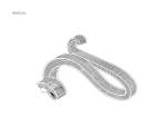
Next, I saved it as a 3ds file and imported it into 3ds Max. I added materials such as a white matte and brushed steel to the panels and metal rods, respectively. I added lights and rendered the scene. The image above is a side by side comparison of the rendered image (top) and the photo of the object (bottom). I’ve also included a perspective line drawing.
sitscape modeling – week 1
Sitscape by Hackenbroich Architects is the object I plan to model for the variable section geometry assignment. It is a seating system that offers the sitter to sit in various positions. The design is based on seven relaxed positions and the smooth transformations between them.

The following shows the process I took for modeling this object in Rhino. I created the geometry at each section cut and lofted them. This is my first pass at modeling this object in Rhino. More to come soon…


You must be logged in to post a comment.